


Thermal noise and calculation of noise number
Noise in electronic circuits is the result of random processes caused by the vibration of atoms at a temperature above zero Kelvin and the flow of electrons and other processes. Noise in an electronic system can be introduced by an external source or generated by the system itself. The level of noise in a system can determine the level of the minimum detectable signal. For this reason, the goal in microwave systems is to minimize the noise level.
Thermal noise is the most dominant noise in microwave systems. The amount of thermal noise power at the input of the receiver is obtained from the following equation. In this relationship, k is Boltzmann’s constant, T is the temperature of the receiver, and B is the instantaneous bandwidth of the receiver. Thermal noise power at a temperature of 290 degrees Kelvin is equivalent to -174 dBm/Hz or -114 dBm/MHz.
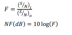
The sensitivity of the receiver is determined according to the current bandwidth and the noise floor of the receiver. Because all the elements inside the receiver produce thermal noise and because of the nature of the noise, the noise of the receiver is usually more than the noise floor. In general, the ratio of the signal-to-noise input of a system to the signal-to-noise ratio of its output is defined as the noise number of that system. In simpler terms, this number represents the amount of noise added to the input signal by the receiver.
NF is important in terms of the amount of noise that a system adds to the background noise of the signal. Also, the gain and noise figure of the first floor are the most important in the receiver. NF is computationally equal to 10 logF, where F is the noise number of the system. The noise figure is defined as the ratio of the input signal to the noise of the receiver to the signal to the output noise and is expressed in dB.
The gain of a system is the ratio of the output signal to the input signal of that system. Therefore, the gain in simple language is the amount of signal level increase.
In the above relationship, F is the noise factor, which represents the linear relationship of the noise number. The initial blocks (closer to the antenna) of the receiver have a greater effect on the noise figure of the receiver. To calculate the total noise figure of the receiver, the noise figure of its blocks cannot be added together, because the gain of the blocks is also effective. Rather, we must first calculate the equivalent noise factor of the receiver and obtain the noise number from that.
The equivalent noise factor of the receiver is obtained from the sum of three parameters, whose relationships and explanations are given. For n floors that are connected consecutively, the overall noise factor caused by the gain and the noise number of the floors is obtained from the following relationship.
In the above relationship, F𝑖 and Gi are the noise factor and the gain of the i-th floor, respectively, both of which are linear in value. The gain and noise figure of all classes must be known before the detector. The noise figure of passive elements is considered equal to their loss in dB, that is, their noise factor is equal to the inverse of their gain. This is because thermal noise is present in both the input and output of these elements, and the noise factor of these elements can be written as the following relationship:

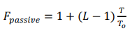
where L is the loss of the element, T is the physical temperature of the element (in Kelvin), T0 is the temperature of the room, which is defined as 290 degrees Kelvin.
Phase noise
In any receiver system, noise is added to the RF signals. Since this noise is additive or additive, the damage caused by it can be reduced by increasing the power of the desired signal. But there is another type of noise whose destructive effect cannot be reduced by increasing the signal power. This noise is not cumulative, but during the process of unwanted modulation, it affects the signal, and most of its effect is on the phase, not the amplitude. This noise is called phase noise. In fact, phase noise is unwanted phase modulation of the signal.
Oscillators, like other circuits, are sensitive to noise. Noise can affect their frequency and amplitude. This effect can be in the form of random changes in the periodicity or deviation of the zero crossing points of the waveform along the time axis. For a normal sine we can write:
![]()
which is a small and random additional phase that shows periodic changes and is called phase noise
In applications, RF measures phase noise in the frequency domain. For an ideal sinusoidal oscillator operating at 𝜔𝑐, the frequency spectrum is like a pulse, while in a real oscillator, the spectrum around the carrier frequency is amplitude. This range is called local oscillator phase noise.
In a receiver, if the LO output contains phase noise, the signal that has been down- or high-frequency mixed will be corrupted. This is shown in the figure below.
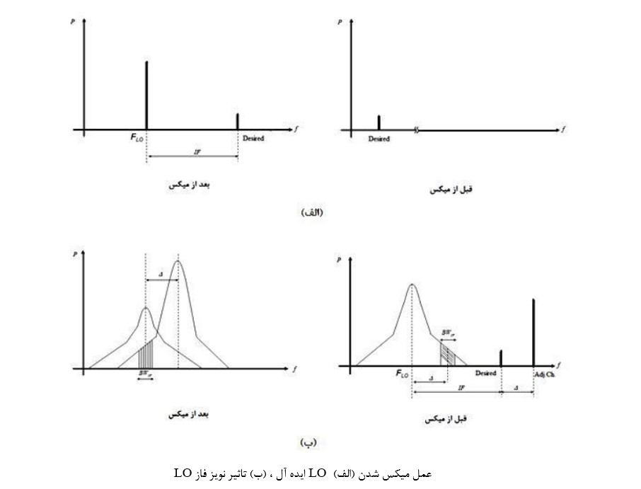
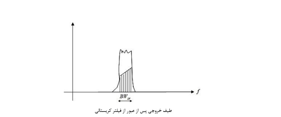
Referring to the ideal state in Figure A above, it can be seen that the desired signal is combined with a pulse and transferred to a lower frequency without changing its shape. But in practice, there may be large interferers in the adjacent channel next to the signal, and the local oscillator has a small phase noise (Figure b). When the desired signal and the signal of the adjacent channel are mixed with LO, the output of the mixer includes two overlapping spectra and cannot be removed with the IF filter. In this way, the desired signal is damaged due to the interference signal. This effect is called bilateral mixing. The effect of two-way mixing on the noise figure of the receiver is shown in the figure below.
To calculate the phase noise, we consider a unit bandwidth at a distance of ∆ω with respect to 𝑐𝜔, power
We obtain the noise in this range and divide it by the average power
SBN: To calculate the phase noise, we consider a unit bandwidth at a distance of ∆ω with respect to 𝜔c, obtain the noise power in this range and divide it by the average power.
Now, for example, if the carrier power is equal to -2dBm and the noise power measured in the range of 1KHz at a distance of 1MHz from the carrier is equal to -70dBm, then the phase noise is -70dBm + 2dBm – 30dBm = -98 dBc/ Hz is obtained. To calculate SBN we have:
![]()
In the above relationship, 𝐿 [𝑑𝐵𝑐⁄𝐻𝑧] is the synthesizer phase noise at the frequency (±) and 𝐵𝑊[Hz] is the width of the system channel. Therefore, the relationship of calculating the selectivity of the system can be expressed as follows:

In the above relationship, SBN is actually the same as L which is expressed as follows. It should also be noted that the CR placed in this relationship is a positive number.