Introducing some type of antennas
Antenna is a telecommunication element and the most essential component of radio equipment, and antennas were first developed by Heinrich Hertz in 1888. The antenna, if used in the transmitter, converts and broadcasts the electrical signal into electromagnetic waves, and if used in the receiver, receives the electromagnetic waves in the space and converts them into an electrical signal and sends them to the circuit for detection. The recipient gives.
Usually, in receivers, each antenna resonates for a specific frequency and produces a specific maximum voltage for that frequency. When the length of the antenna is proportional to the wavelength of the received wavelength, the wave is completely placed in the antenna and so called the antenna has become resonant or in a state of resonance. It means that the antenna is synchronized with the received wave and in this case the voltage that reaches the antenna is maximum. Of course, it is not necessary that the length of the antenna must be exactly equal to the received wavelength, because in order to solve this problem, a coil is added to the antenna along with one or two compression elements such as a variable capacitor to create a resonance mode in the antenna.
Antennas have various structures that are determined according to the required application. In fact, antennas are divided into the following three categories.
- Physical structure of the antenna
- Frequency range
- Applications
Physical structure of the antenna
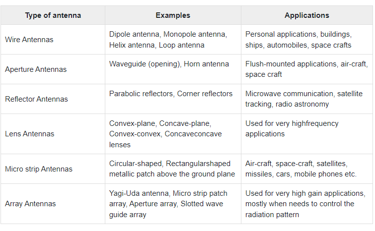
Below are the types of antennas based on physical structure.
- wired antennas(dipole, monopole, helix, loop, etc.)
- Aperture antennas (Waveguide and Horn antennas)
- Reflector antennas
- Lens antennas
- Microstrip antennas
- Array antennas
Frequency range
Below are the types of antennas based on the working frequency.
- Very Low Frequency(VLF)
- Low Frequency (LF)
- Medium Frequency (MF)
- High Frequency (HF)
- Very High Frequency (VHF)
- Ultra High Frequency (UHF)
- Super High Frequency (SHF)
- microwave
- Radio frequency
Applications
Below are the types of antennas according to the modes of use.
- Point-to-point communication
- Broadcast applications
- Radar communications
- Satellite communications
A suitable antenna is required for each radio wavelength and they cannot be used interchangeably. For example, you cannot use a radio antenna instead of a Wi-Fi antenna. One of the simplest possible antennas is known as a half-wave dipole. This antenna is half a wavelength long and is made of two halves, each half is actually a quarter of the radio wavelength we want, and each half is A single conductor is fed separately.
For example, for a 3.14 MHz wave, a dipole antenna should be 4895.10 meters. As you can guess from its name, this bipolar has two parts, each part is 24476.5 meters long. pay attention! These lengths are calculated in theory. Antennas are not always made to the exact theoretical length, as this amount of manufacturing precision is not possible.
Some type of antennas
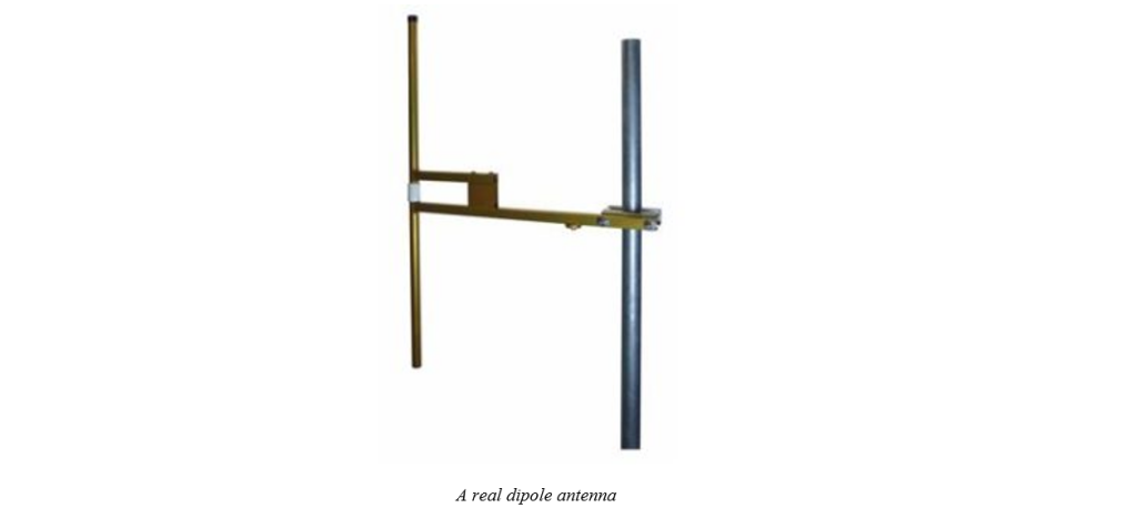
1.Dipole antenna
Dipole antenna is one of the simplest antennas. This antenna consists of two metal rods, each of which has a length of λ/4. This structure is shown in the figure below.

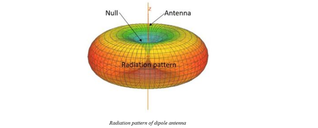
The radiation pattern of the dipole antenna is shown in the figure below. According to this figure, in the direction of the antenna, the field is equal to zero and is symmetrical in the horizontal plane. Therefore, this antenna looks like an omni-directional antenna in the horizontal plane. The gain of this antenna is less than 3dB and its polarization is linear and in line with its bars. Also, this antenna has a small frequency bandwidth and its value does not exceed a few percent.
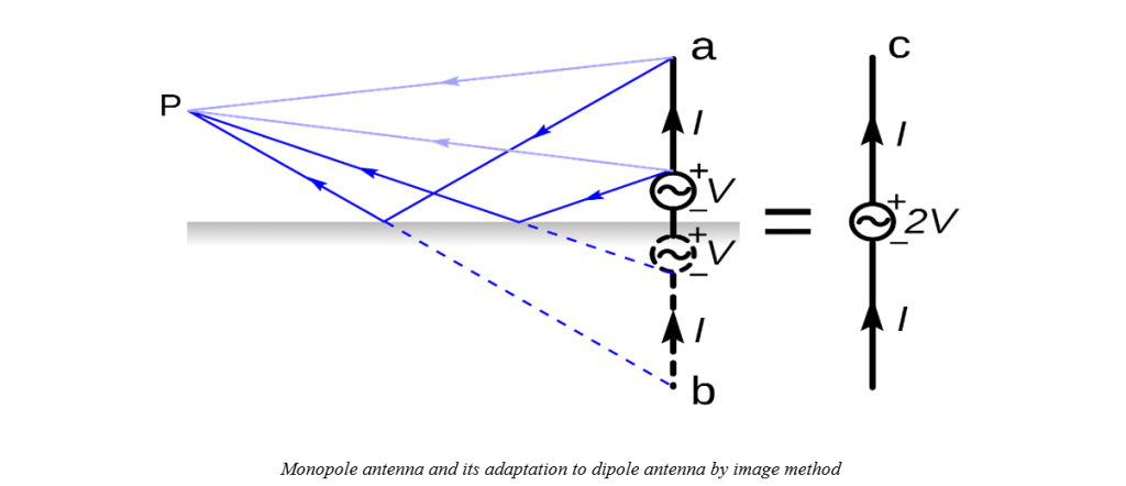
2.Monopole antenna
A monopole antenna is a type of antenna that is in the form of a rod and is placed on top of a conductive plate and is usually perpendicular to it. The mentioned plane is called the earth plane. So the meaning of ground in this type of antennas is different from conventional ground. The power supply in these types of antennas is placed between the rod and the ground, and one end is connected to the rod and the other end is connected to the ground. This antenna is in front of the dipole antenna, which has two rods, and the power source is placed between those two rods.
According to the image method, this antenna has the function of a dipole antenna with twice the length of this antenna. In this way, the wave from space either directly hits the antenna rod itself as if it hit the upper half in a dipole antenna, or it hits the ground and then reflects to the rod as if it hit the lower half of the antenna in a dipole antenna.
The advantage of this antenna compared to the dipole antenna is its smaller dimensions, which has increased its use in practical cases. These antennas are also used in cars, in which case the roof of the car acts as a ground plane. Obviously, in this case, the antenna rod is not completely horizontal.
In this antenna, like a dipole antenna, in order to know what the pattern is like, we need to know how many times the length of the antenna is the wavelength. For example, monopole antennas whose length is less than a quarter of the wavelength have only one lobe.
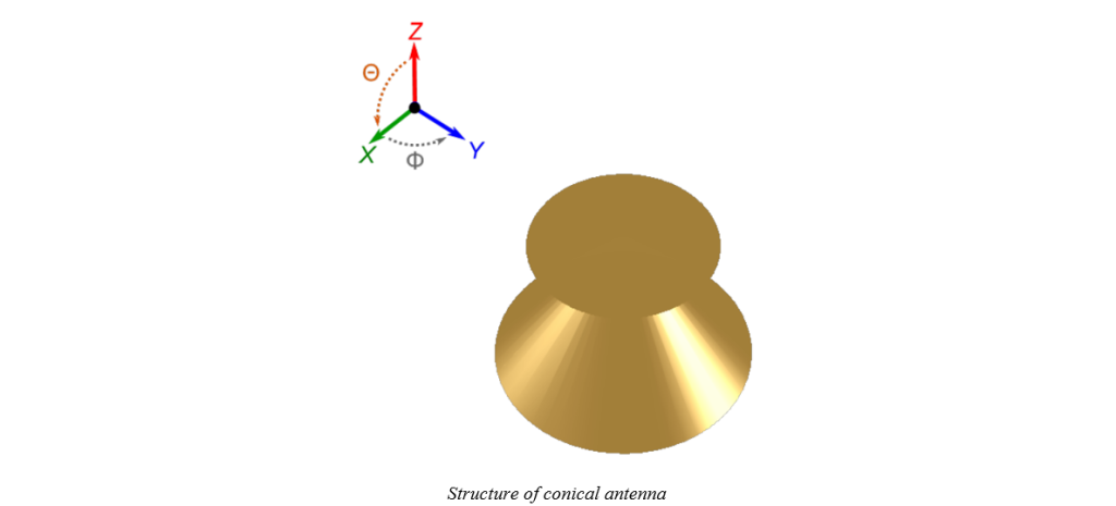
3.Conical antenna
This antenna is a monopole variation of a bi-cone antenna. So that it consists of a circular plane of the earth and a cone, the top of the cone is placed near the center of the disk. This antenna is used when the physical size needs to be reduced or the radiation is mainly in a half distance.
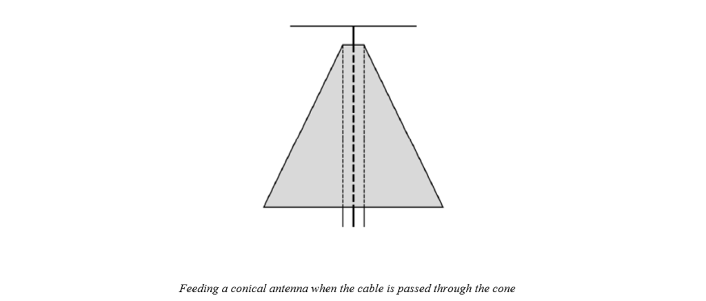
Feeding this antenna according to its direction is possible in two ways, feeding through a coaxial cable that passed through the cone or feeding through a coaxial cable that passed through the disc. In the first case, the outer conductor is connected to the top of the cone and the inner conductor is connected to the disc, but in the case that the cable passes through the disc, the outer conductor of the cable is connected to the disc and the inner conductor is connected to the cone.
4.Biconical antenna
We saw that the dipole antenna has a constant gain in the horizontal direction and it is almost an omnidirectional antenna. However, its interest is low. If we want to maintain the omnidirectional structure but increase the gain at the same time, we can use double cone antenna. Double-cone antennas, as their name suggests, consist of two metal cones that are similar to each other. In fact, these antennas are a kind of modified dipole antenna and the purpose of performing these modifications on dipole antennas is to achieve
More bandwidth without more complexity. For this reason, these antennas are famous for three characteristics: large impedance bandwidth, omnidirectional radiation, and simplicity in design and installation. The feeding of these antennas is usually done through a coaxial cable that has passed through one of the cones and reached the center. The energy from the feeding place on the surface of the cones will move from the top of the cone to the base and finally radiate. At high frequencies, this antenna behaves like an infinite double-cone antenna.
The two-cone antenna has a narrow beam in the height direction, but it has a uniform gain in the direction of the direction. These antennas can have a gain of up to 10 dB. The highest to lowest frequency ratio is 4 to 1. It is possible to make these antennas up to 40 GHz frequency. But this antenna is single-polarized, and if it is necessary to receive both polarizations, we must use polarizing plates.

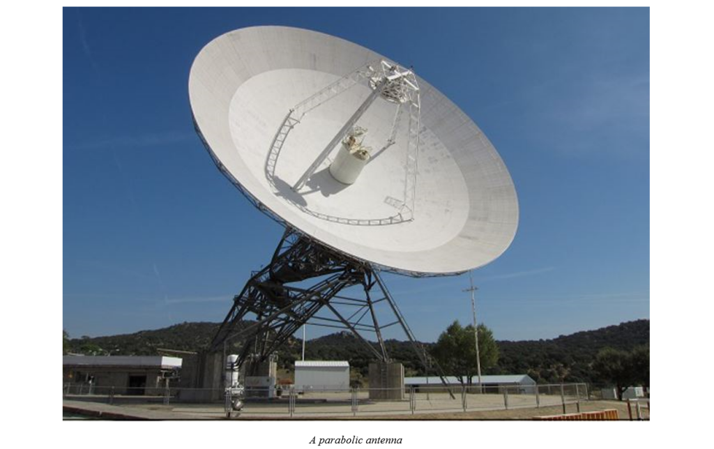
5.Parabolic antenna
Parabolic antennas are among the most widely used antennas in all fields of telecommunications, radar and electronic warfare. Parabolic antennas consist of a parabolic section and a relatively simpler antenna located at the center of this parabola. The parabolic section concentrates the field at the focus and then the antenna at the focus converts this field into voltage or current.
Parabolic antennas have a very narrow beam and high gain. Their beam width can be between 0.2 degrees and 10 degrees. The gain is between 20dB and more than 40dB. This small beam width makes the antennas ideal for orientation, but on the other hand, the probability of listening to these antennas is low. The polarization of parabolic antennas is the same as the polarization of the antenna placed in the focus, and the parabolic part itself has no effect on the polarization. The frequency bandwidth of these antennas is average and is about 30%.
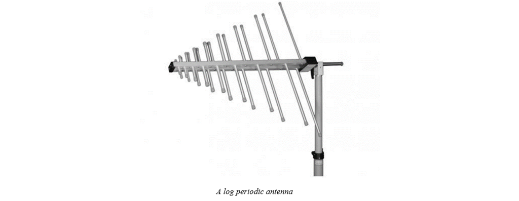
6.Log periodic antenna
Log periodic antennas are actually extensions of dipole antennas. In these antennas, by placing several dipoles with different lengths and distances, resonance mode is created. This mode increases the gain of the antenna and makes its pattern somewhat directional.
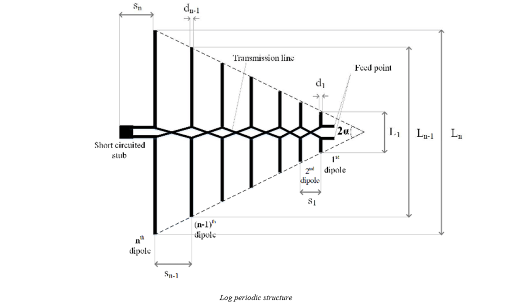
Log periodic antennas have linear polarization and this polarization is in line with the antenna rods. The gain of the antenna is between 5 and 15 dB and the beam width is 30 to 50 degrees. The most important feature of these antennas is the frequency bandwidth of this antenna, the ratio of the highest to the lowest frequency is equal to 10.
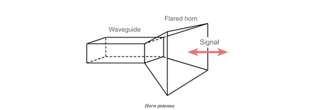
7.Horn antenna
Horn antenna is actually a waveguide development. An open waveguide acts as an antenna and creates a wave in open space. The presence of a horn at the output of the waveguide makes us have more gain and less beam width. The figure below shows the simplified structure of a horn antenna.
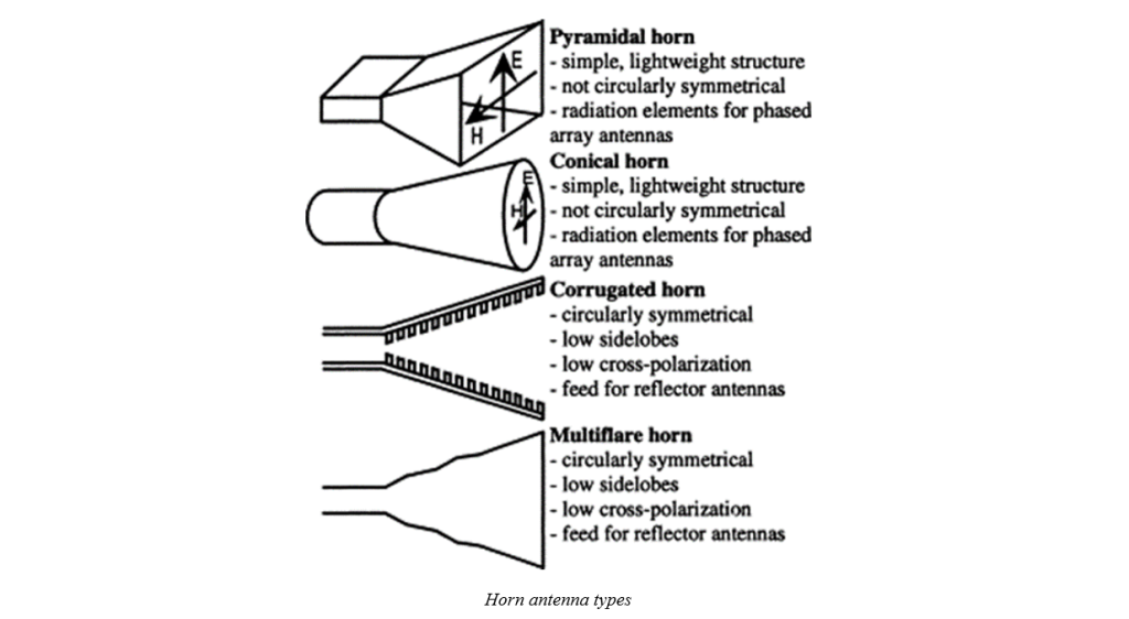
Since the horn antenna consists of flat plates, it is possible to make it with high precision. For this reason, these antennas can be produced for very high frequencies (up to 40 GHz or higher). Horn antennas usually have linear polarization, but by adding a polarizing plate, both polarizations can be received. However, using a polarizer causes losses in the transmitted signal. The gain of horn antennas is between 5 and 20 dB and the beam width is between 10 and 40 degrees. In a typical horn antenna, the ratio of the highest frequency to the lowest is 2 to 1. However, this bandwidth can be increased with methods. The following figure shows the types of horn antennas:
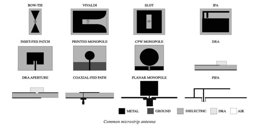
8.Microstrip antenna
The microstrip antenna is a relatively modern invention. The antenna was invented to allow the convenient integration of an antenna and other drive circuitry of a communication system on a common printed circuit board or semiconductor chip. In telecommunications, a microstrip antenna (also known as a printed circuit antenna) usually refers to an antenna fabricated on a printed circuit board (PCB) using photolithography techniques. They are mostly used at microwave frequencies. A discrete microstrip antenna consists of a metal neutral patch of various shapes (a patch antenna) on a PCB (printed circuit board) surface with a metal neutral ground plane on the other side of the board.
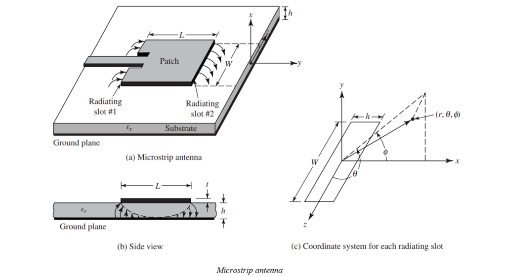
Most microstrip antennas consist of several patches in a two-dimensional array. The antenna is usually connected to the transmitter or receiver via neutral microstrip transmission lines. A radio frequency current is applied between the antenna and the ground plane (or generated in the receiver antennas of the received signal). Microstrip antennas in recent decades due to their thin planar cross-section that can be incorporated into the surfaces of consumer products, airplanes, and rockets; the ease of making them using printed circuit techniques; The ease of integrating the antenna on the same board as the rest of the circuit and the possibility of adding active devices such as microwave integrated circuits to the antenna itself to make active antennas have become very popular.
Common microstrip antenna shapes are square, rectangular, circular, and oval, but any other continuous shape is possible.